Power Devices for supplying of consumers in contact wire voltage networks with DC and AC voltage
- Testing and commissioning of DC and AC motors
- Simultation of catenary voltages or fluctuations
- Feeding into local contact wire voltage networks and Zugsammelschienen
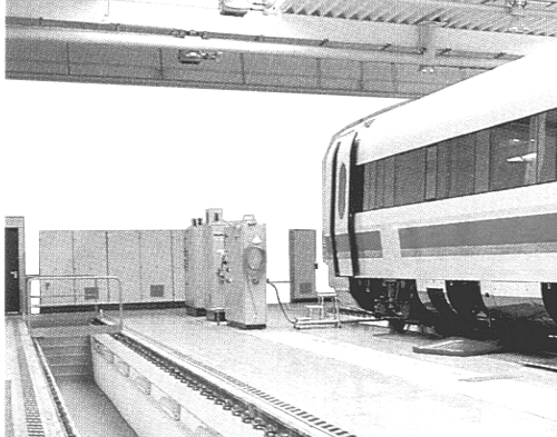
- Inspection of engine vehicles
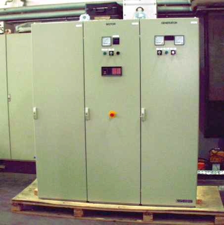
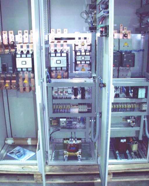
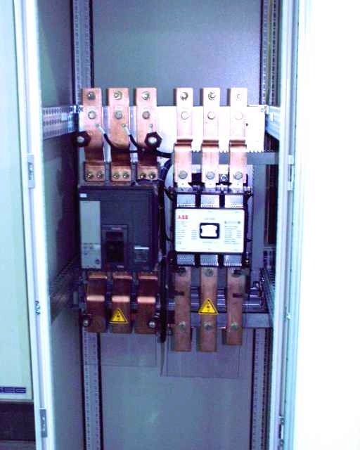
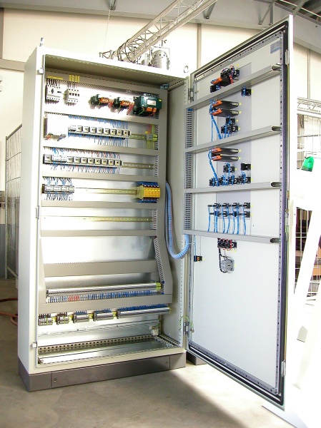
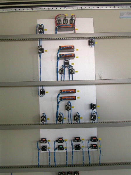
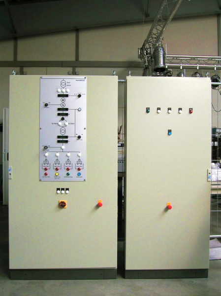
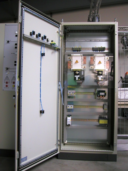
The Series DB UIC has been specially developed for the simulation of contact wire voltage networks and the commissioning and testing of electrical loads which are operated under these network conditions. The device series enables continuous regulation of the output voltage in several voltage ranges (AC and DC) of 500V ... 4200V without power reduction. Extensive monitoring and protection devices ensure reliable operation of these systems at optimum protection for the operator. Depending on the version and scope of supply is the simultaneous supply of several railway lines possible when switching under full load.
Technical Specifications for Series DB-UIC 4200:
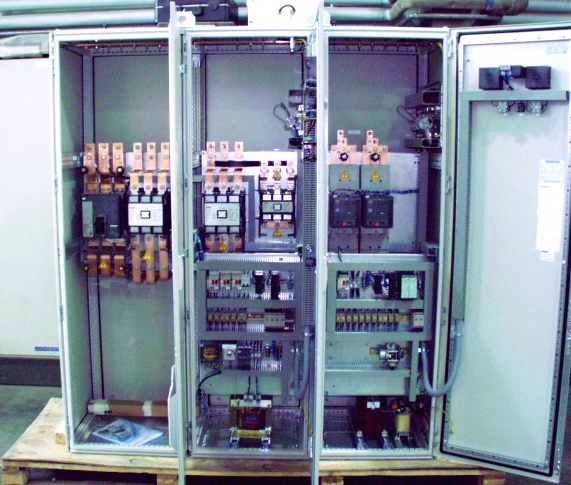
- Range selection through fixed transformers with secondary-side pin
- Transformer with plus / minus adjustment for voltage regulation
- Motorized readjustment, drive via frequency converter
- Medium voltage switch for area code, and AC / DC Switching
- Bridge rectifier with a high blocking voltage (9600V)
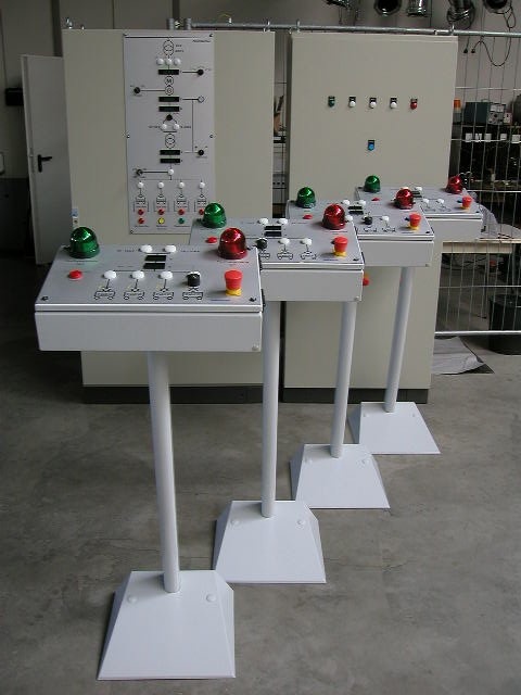
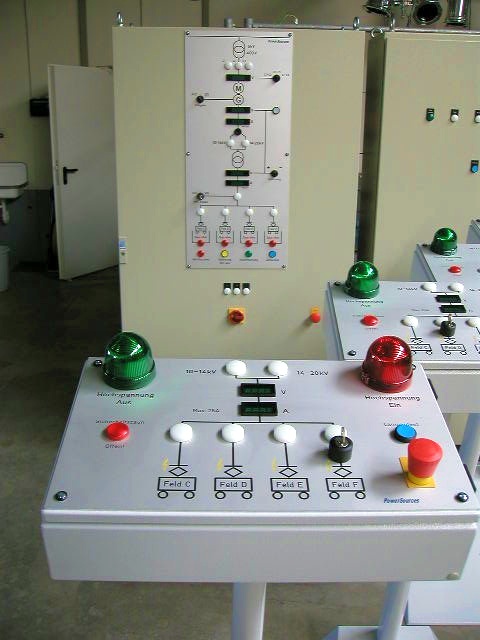
- Control optional in separate control cabinet
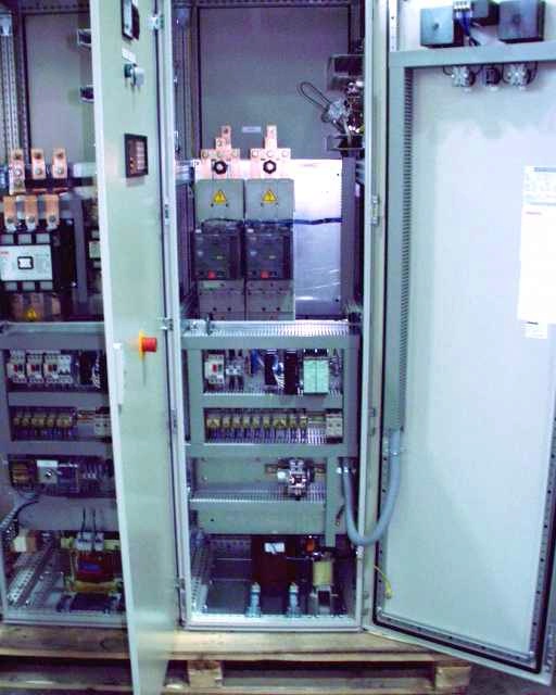
- Service-friendly construction
Options:
- Multiple output:
Switching to different exit points. External panels offer full remote control with mutual locking. The operating status is also displayed on the inactive panels. Connecting the external control panels via 25-pin control cable. Installation in 19 "bench top (3U, 300mm deep) - Powershift:
Extraction point is switched on and off under full load
| Power Input | 3 x 400V / 50Hz |
| Output Voltage | 500…4200V, adjustable, divided into six voltage ranges: |
| AC: | 1: 500…1300V AC 2: 900…2000V AC 3: 1700…4200V AC |
| DC: | 4: 500…1300V DC 5: 900…2000V DC 6: 1700…4200V DC |
| Output Current | max. 300A |
| Output Power | 150kW at all output voltages |
| Ripple (DC) | typ. 4.2% |
| Regulation | voltage regulation |
| Implementation | according to VDE and VBG 4 |
| Controls | main switch Emergency stop button key switch Button for ON / OFF 10-turn potentiometer for voltage selection Button for range selection Digital voltmeter 4 ½ digits for voltage, current and power All status indicators via potential-free contacts |
| Case | Triple steel cabinet |
| Dimensions (WxDxH) | approx. 3600x1000x2100 mm |
| Cooling | by filter fans |
| Output | threaded bolt |
| Remote Control | 25pol. terminal Block |
Documentation:
- Circuit diagram
- terminal plan
- bill of materials
- Summary of Balance statement
Final tests:
- Endurance test at idling speed (U-Control)
- Endurance test in short circuit (I control)
- Last experiment in continuous operation (full- and overload)

